1、The valve gear comprises the valve group and the valve driving group.
Key components of the valve group include: the valve, its guide, stem seal, spring, spring retainers, and locking mechanism (valve locks).
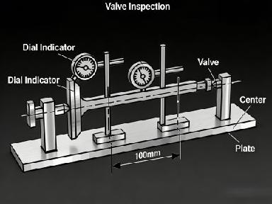
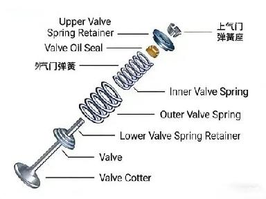
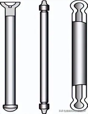
Valve - Seals the combustion chamber and controls the intake of fuel and the exhaust of gases in the engine. It is divided into intake valves and exhaust valves.
Valve Guide - A guiding device for engine valves, installed on the cylinder head.
Valve Stem Seal - Used to seal the engine valve stem, preventing oil from entering the intake or exhaust pipes and causing oil loss.
Valve Spring - Ensures the valve closes promptly and fits tightly, preventing it from bouncing due to engine vibration, which could compromise its seal.
Valve Spring Retainer - Includes an upper and lower retainer. Its main function is to transfer the tension of the valve spring to the valve mechanism, ensuring a proper seal between the valve and valve seat.
Valve Locks (Keepers) - To allow the valve to return under the force of the valve spring, valve locks are used to secure the valve in place.
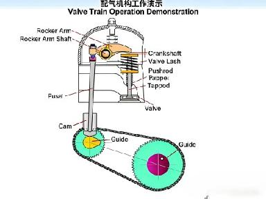
2. Valve Actuating Assembly
The valve actuating assembly primarily consists of the camshaft, valve tappet/lifter, valve bucket (shim), valve rocker arm, rocker shaft, camshaft timing gear/sprocket, and pushrod.
The camshaft, equipped with cam lobes, governs the precise timing of valve opening and closing.
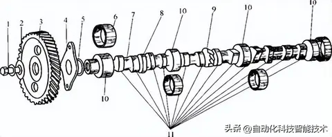
图示组件 (Diagram Components):
1 — Bolt
2 — Washer
3 — Timing Gear
4 — Thrust Flange
5 — Flange Seat/Housing
6 — Camshaft Bushing/Bearing
7 — Camshaft
8 — Eccentric (for Fuel Pump Drive)
9 — Helical Gear (for Distributor Drive)
10 — Camshaft Journal
11 — Cam (Lobe)
气门挺柱 (Valve Tappet/Lifter):
Solves the issues of impact and noise caused by valve clearance, and is controlled by engine oil pressure.
气门顶杯 (Valve Bucket/Shim):
Installed on the top of the valve. It also allows for automatic valve clearance adjustment (oil-pressure controlled) and helps reduce valve wear.
气门摇臂 (Rocker Arm):
Transfers force from the camshaft to control the opening and closing of the valve.
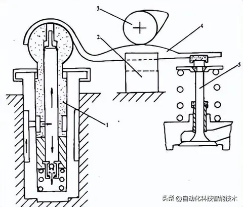
图示组件 (Diagram Components):
1 — Hydraulic Lifter
2 — Guide Slot/Channel
3 — Camshaft
4 — Floating Rocker Arm
5 — Valve
摇臂轴 (Rocker Arm Shaft):
Installs the rocker arm, which pivots around it.
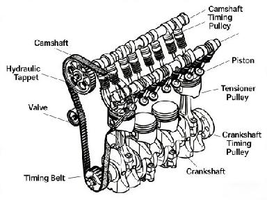
凸轮轴正时齿轮 (Camshaft Timing Gear/Sprocket):
Receives force from the crankshaft timing gear via a drive belt (or chain), transmitting this power to the camshaft to control the proper opening and closing of the valves.
气门推杆 (Push Rod):
Transfers force from the camshaft to the rocker arm (used in mid-location and overhead valve pushrod engine designs).